4:56 PM
Apparently it's not *that* hard...
To start, here's the buzz:
http://forums.vwvortex.com/zerothread?id=604403
http://forums.vwvortex.com/zerothread?id=608799
http://futrellautowerks.com/projects/89clvr6.htm
Parts:
http://futrellautowerks.com/01partscatalog/hybrid/mk3.htm
To start, here's the buzz:
http://forums.vwvortex.com/zerothread?id=604403
http://forums.vwvortex.com/zerothread?id=608799
http://futrellautowerks.com/projects/89clvr6.htm
Parts:
http://futrellautowerks.com/01partscatalog/hybrid/mk3.htm
8:48 AM
All iPods are broken. In this article I'll explain how to fix your iPod. "My iPod's not broken, it plays my music just fine!" Oh you-that-have-been-bought-by-expensive-apple-marketing, read on.
Try this: first, update your iTunes library on your iPod, like you do every morning. Then, simulate a catestrophic failure of your computer's hard-drive (a not-so-uncommon event) by throwing your computer into a lake or something. "Not to fear - my iTunes library is on my iPod, right?!" Wrong. Now connect your iPod to your other computer, start-up iTunes, and click the "Restore My iTunes Library" button. "Ok, just a second... uh... wait, that button doesn't exist!" Exactly.
Apple prevents you from "pulling" your very own music off of your iPod onto your computer. You can only "push" it on. No engineer would purposefully omit such an obvious feature from the iPod - it must be broken!
[more to come]
iPods run on an ARM7TDMI processor.
iPods can be controlled over a serial bus using the Apple Accessory Protocol.
iPod connectors have a 30-pin connector.
11:00 AM
This post outlines the steps for changing the timing belt on a VW Mk3 2.0L engine. I did it on my 1997 Golf GL. I used Keith Kozma's post as a reference, plus the Haynes manual (which sucks), and posts from vwenthusiast.com, vwvortex.com, and google groups. After replacing the belt, I found Dan Marinucii's article on setting the timing of VW 2.0L "ABA" engines extremely helpful.
I didn't use a Bently manual; perhaps that's why this job took me the whole weekend. Also, buy a fricking impact wrench. It's worth the $$$ you'll save by doing it all yourself. I found one at OSH for $150.
Finally, all of the images in this post have links to higher res photos. Click on an image for more detail. Ok, let's start.
Jack Up Your Car
Start by jacking up the passenger side of the car and removing the right front wheel (figure 1). This will make it much easier to access the lower crank pulley.
Remove the Splash Guard
Once the wheel is removed the plastic splash guard will be visible. It is affixed to the chassis by two sprung fasteners and a plastic tab. To remove the splash guard, start by simply yanking the fasteners off their screw post. The first will be clearly visible as pictured in figure 2. Yank it off. The second fastener is kind of hidden underneath and toward the front. Best access is from the front of the car. Yank it off too. Finally, slide the plastic tab out (figure 3) and the cover will fall off.
At this point the crank pulley and belts should be clearly visible and easily accessible. We're ready to go to work.
Remove Air Intake
Removing the Air Filter Housing and perhaps the Air Intake Hose will make accessing the belts and pulleys much easier from up top. Remove the air filter housing by unclipping the two clips located on either side, removing the three hoses (two small, one larger) on the engine side of the housing, disconnecting the electrical sensor, and lifting the housing up and out (figure 5). At this point, the air filter housing can be moved out of the way. However, I completely removed the assembly by disconnecting the air intake hose at the intake manifold (figure 6).
Remove Upper Timing Belt Cover
Once the air intake is out of the way, removing the upper timing belt cover is easy. Just unclip the two clips on either side of the cover and lift it off.
Remove V Belt
Next we're going to remove the V Belt, which drives the oil and water pumps off of the main crank pulley. Do do this, we'll need to release tension on the belt by loosening the oil pump. Loosen the oil pump tensioner bolt (13mm, figure 9), the stabilizing bolt (13 mm, figure 10), and the main bolt (16mm, figure 11). The oil pump should rotate on the main bolt and release the tension on the V belt. If it's stuck, use the tensioner bolt to rotate the sprockets that rotate the oil pump to remove tension.
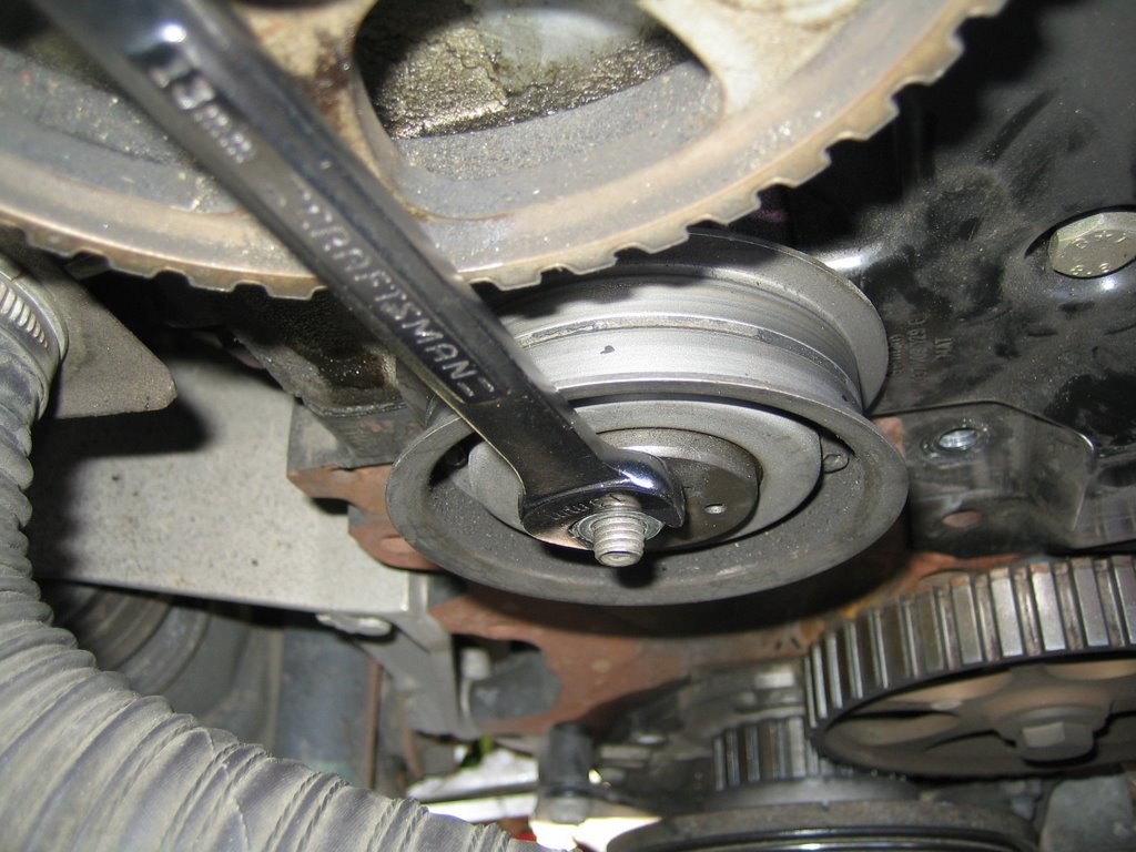
Remove Ribbed Drive Belt
Next we'll remove the ribbed drive belt. The ribbed drive belt is tensioned by an automatic spring tensioner. To remove the drive belt, just release the tension on tensioner pulley by inserting a long screw driver between the pulley and tensioner arm. Use the leverage to pull back and slide the belt off.
Orient to TDC
Before we go any further, we'll orient the crank and cam to TDC. It does not have to be exact at this point. Gettting it close will just make things easier later.
Make sure the car is not in drive and just to be safe, disconnect the battery's negative terminal. Using a wrench, rotate the cam shaft until the "OT" marks on the camshaft sprocket line up with the "OT" arrow imprinted on the engine head. This will ensure that when we replace the timing belt we'll be darn near close to TDC and will make verifying TDC after replacing the belt much easier.
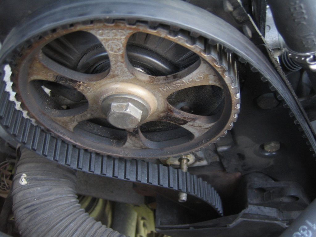
Remove Crank Pully
No that the we're at or close to TDC we can remove the lower crank pully to gain access to the lower portion of the timing belt cover. The crank pulley is shown here before the other belts have been removed. Notice the 4 hex bolts. Try and remove those rather than the main crank bolt. They're 6MM Hex bolts. USE AN IMPACT WRENCH TO AVIOD STRIPPING! I didn't use an impact wrench and ended up stripping the 4th bolt. AGH! So I was relegated to buying one and removing the main crank bolt instead.
The major advantage to removing the 4 Hex bolts instead of the crank bolt is that we are able to gain access to and remove the lower timing belt cover without removing the lower crank shaft sprocket. Because I had to take off the crank bolt, the toothed sprocket came off too, which made re-orienting to TDC afterward much more of a pain.
Either way, once the lower pulley is removed we can then remove the lower cover which will then allow us to remove the belt.
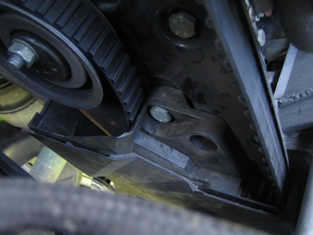
Remove Lower Timing Belt Cover
Alright, with the crank pulley out of the way we can take off the lower timing belt cover. There are four bolts we'll have to access.
The first two are located directly in front of you as your looking at where the crank pulley used to be. I think the're 5MM Hex bolts. Remove them.
The next bolt is up top near the cam sprocket. It's a 1/2" (or 10 mm?) bolt.
The last is a nut that needs to be removed that is hidden midway down near the water pump. You'll have to reach to see, but it's there.
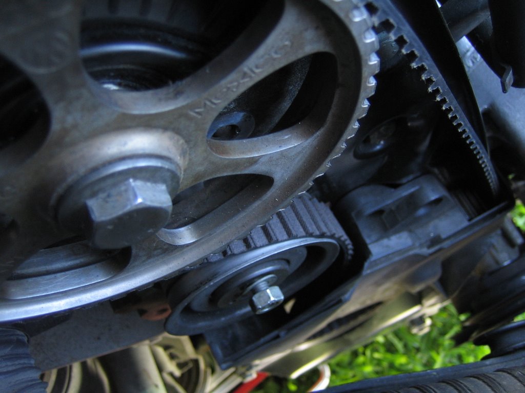
With the lower portion of the belt cover off, we have full access to the timing belt and can see the three main sprockets: the cam sprocket up top, the distributor sprocket in the middle, and the crank sprocket down low.
Replace Timing Belt
To remove the timing belt, release the tension on the timing belt tensioner by unscrewing its 13mm nut a bit. Once the tension has been released carefully slide off the timing belt doing your best not to move any of the three sprockets.
Slide on the new belt, but don't re-tension it. Leave it slack.
Verify TDC Alignment
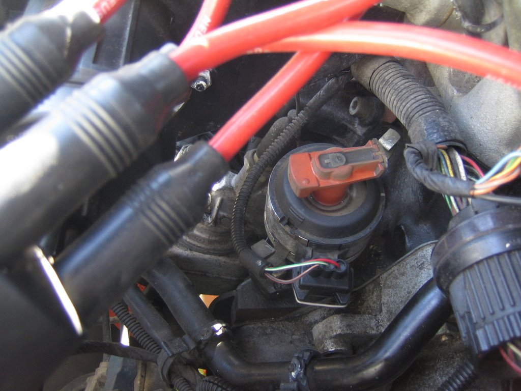
Ok, at this point we'll verify that the Cam, Distributor, and Crank are all aligned at TDC.
The cam hould already be close to TDC. To set it at TDC line up the sprocket "valley" between the "OT" with the "OT" arrow on the engine block. See Figure xx.
To set the distributor at TDC take the distributor cap off and line up the dirtributor arm with the small groove in the distributor housing. The distributor arm should be facing the engine block. See Figire XX. Once aligned, take a bright permanent marker or whiteout and make a TDC reference on the distributor sprocket.
To set the crank at TDC remove the green plug on the [transaxle?] housing. The flywheel should be visible. There is a small mark on the flywheel that, when aligned with the "V" on the opening, sets the crank at TDC. See Figure XX.
Put It All Back Together
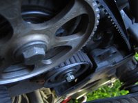
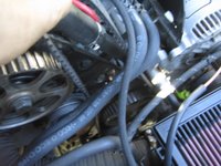
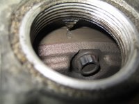


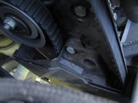
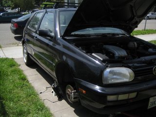 figure 1 |
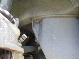 figure 2 |
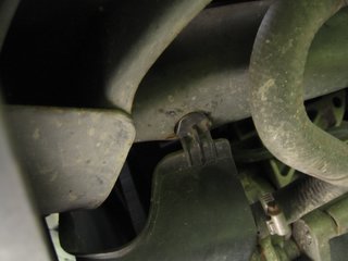 figure 3 |
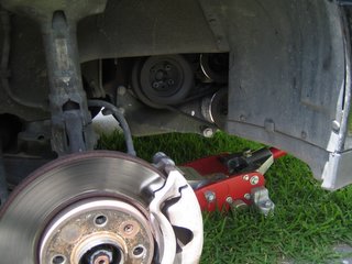 figure 4 |
Finally, all of the images in this post have links to higher res photos. Click on an image for more detail. Ok, let's start.
Jack Up Your Car
Start by jacking up the passenger side of the car and removing the right front wheel (figure 1). This will make it much easier to access the lower crank pulley.
Remove the Splash Guard
Once the wheel is removed the plastic splash guard will be visible. It is affixed to the chassis by two sprung fasteners and a plastic tab. To remove the splash guard, start by simply yanking the fasteners off their screw post. The first will be clearly visible as pictured in figure 2. Yank it off. The second fastener is kind of hidden underneath and toward the front. Best access is from the front of the car. Yank it off too. Finally, slide the plastic tab out (figure 3) and the cover will fall off.
At this point the crank pulley and belts should be clearly visible and easily accessible. We're ready to go to work.
Remove Air Intake
Removing the Air Filter Housing and perhaps the Air Intake Hose will make accessing the belts and pulleys much easier from up top. Remove the air filter housing by unclipping the two clips located on either side, removing the three hoses (two small, one larger) on the engine side of the housing, disconnecting the electrical sensor, and lifting the housing up and out (figure 5). At this point, the air filter housing can be moved out of the way. However, I completely removed the assembly by disconnecting the air intake hose at the intake manifold (figure 6).
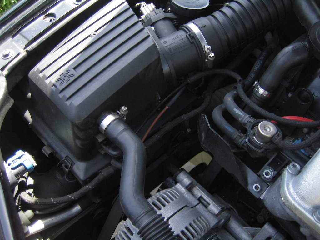 figure 5 |  figure 6 |
Remove Upper Timing Belt Cover
Once the air intake is out of the way, removing the upper timing belt cover is easy. Just unclip the two clips on either side of the cover and lift it off.
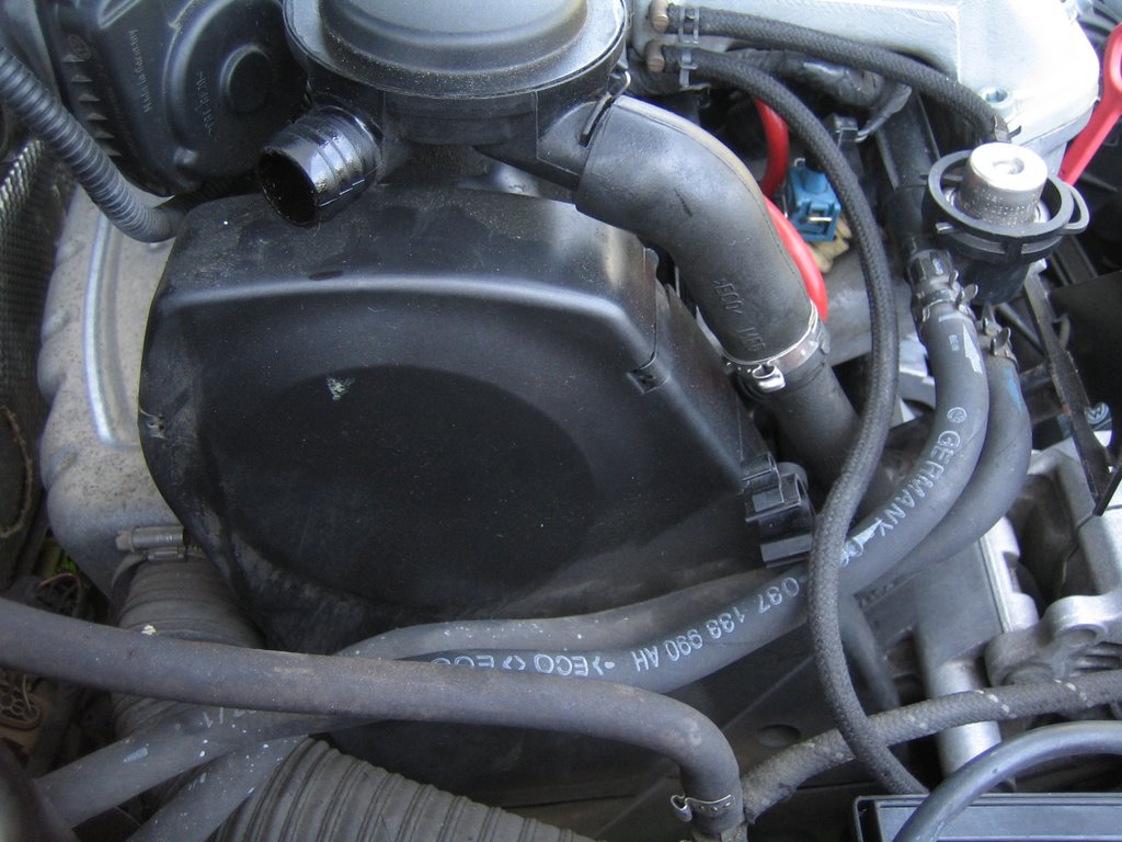 figure 7 | 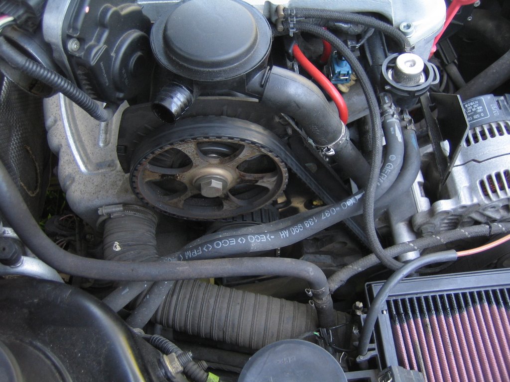 figure 8 |
Remove V Belt
Next we're going to remove the V Belt, which drives the oil and water pumps off of the main crank pulley. Do do this, we'll need to release tension on the belt by loosening the oil pump. Loosen the oil pump tensioner bolt (13mm, figure 9), the stabilizing bolt (13 mm, figure 10), and the main bolt (16mm, figure 11). The oil pump should rotate on the main bolt and release the tension on the V belt. If it's stuck, use the tensioner bolt to rotate the sprockets that rotate the oil pump to remove tension.
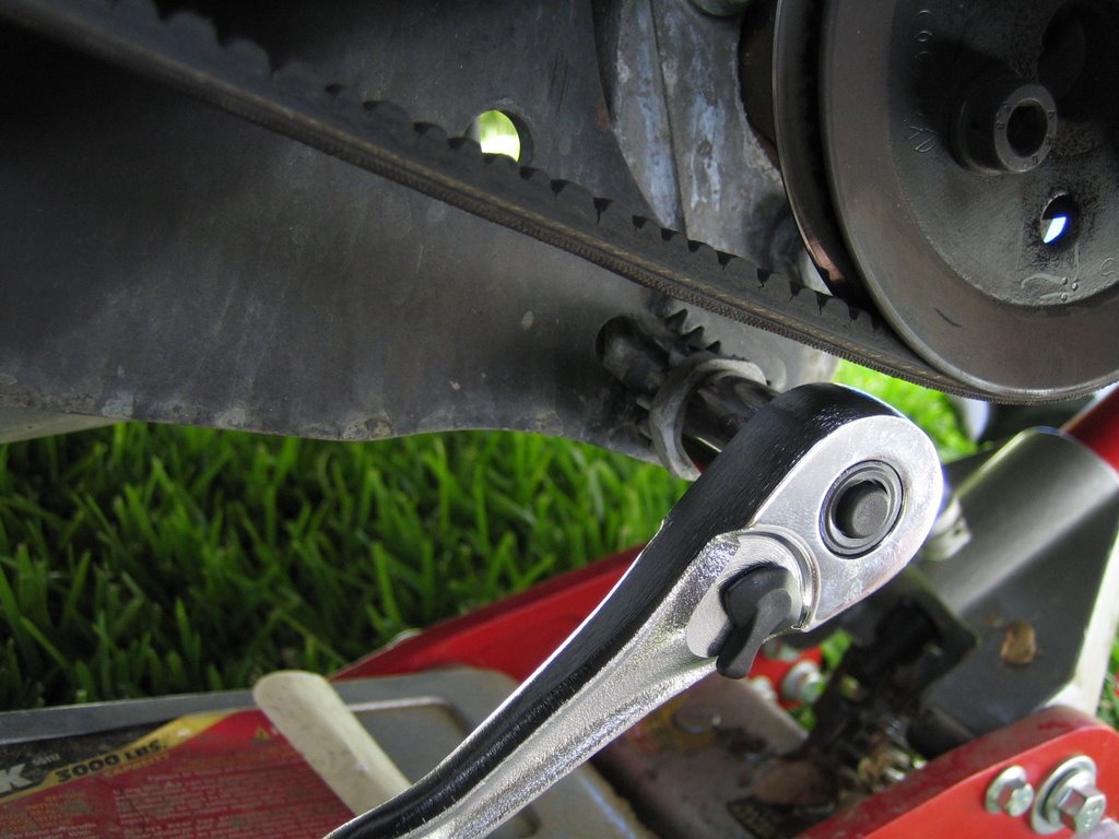 figure 9 |  figure 10 |
 figure 11 | 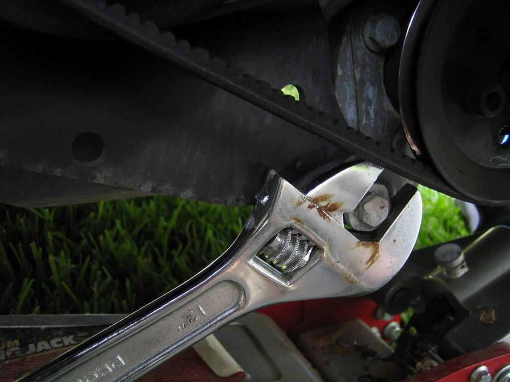 figure 12 |
 figure 12 |
Next we'll remove the ribbed drive belt. The ribbed drive belt is tensioned by an automatic spring tensioner. To remove the drive belt, just release the tension on tensioner pulley by inserting a long screw driver between the pulley and tensioner arm. Use the leverage to pull back and slide the belt off.
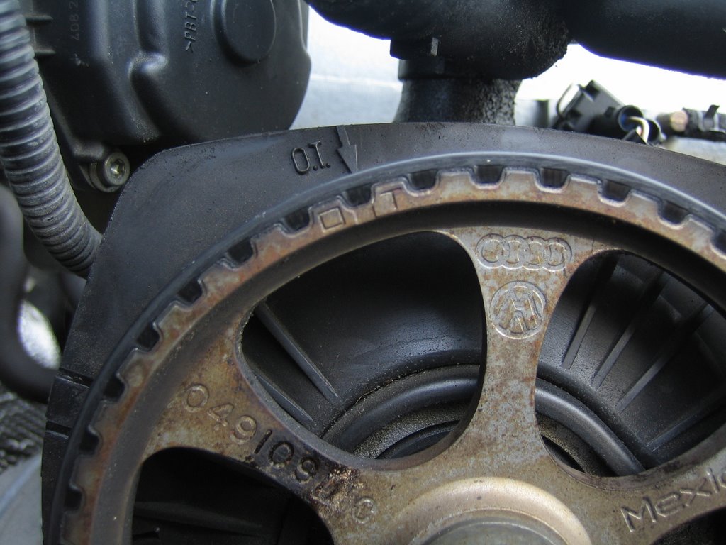 figure 13 |
Before we go any further, we'll orient the crank and cam to TDC. It does not have to be exact at this point. Gettting it close will just make things easier later.
Make sure the car is not in drive and just to be safe, disconnect the battery's negative terminal. Using a wrench, rotate the cam shaft until the "OT" marks on the camshaft sprocket line up with the "OT" arrow imprinted on the engine head. This will ensure that when we replace the timing belt we'll be darn near close to TDC and will make verifying TDC after replacing the belt much easier.
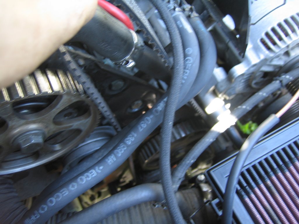
Remove Crank Pully
No that the we're at or close to TDC we can remove the lower crank pully to gain access to the lower portion of the timing belt cover. The crank pulley is shown here before the other belts have been removed. Notice the 4 hex bolts. Try and remove those rather than the main crank bolt. They're 6MM Hex bolts. USE AN IMPACT WRENCH TO AVIOD STRIPPING! I didn't use an impact wrench and ended up stripping the 4th bolt. AGH! So I was relegated to buying one and removing the main crank bolt instead.
The major advantage to removing the 4 Hex bolts instead of the crank bolt is that we are able to gain access to and remove the lower timing belt cover without removing the lower crank shaft sprocket. Because I had to take off the crank bolt, the toothed sprocket came off too, which made re-orienting to TDC afterward much more of a pain.
Either way, once the lower pulley is removed we can then remove the lower cover which will then allow us to remove the belt.
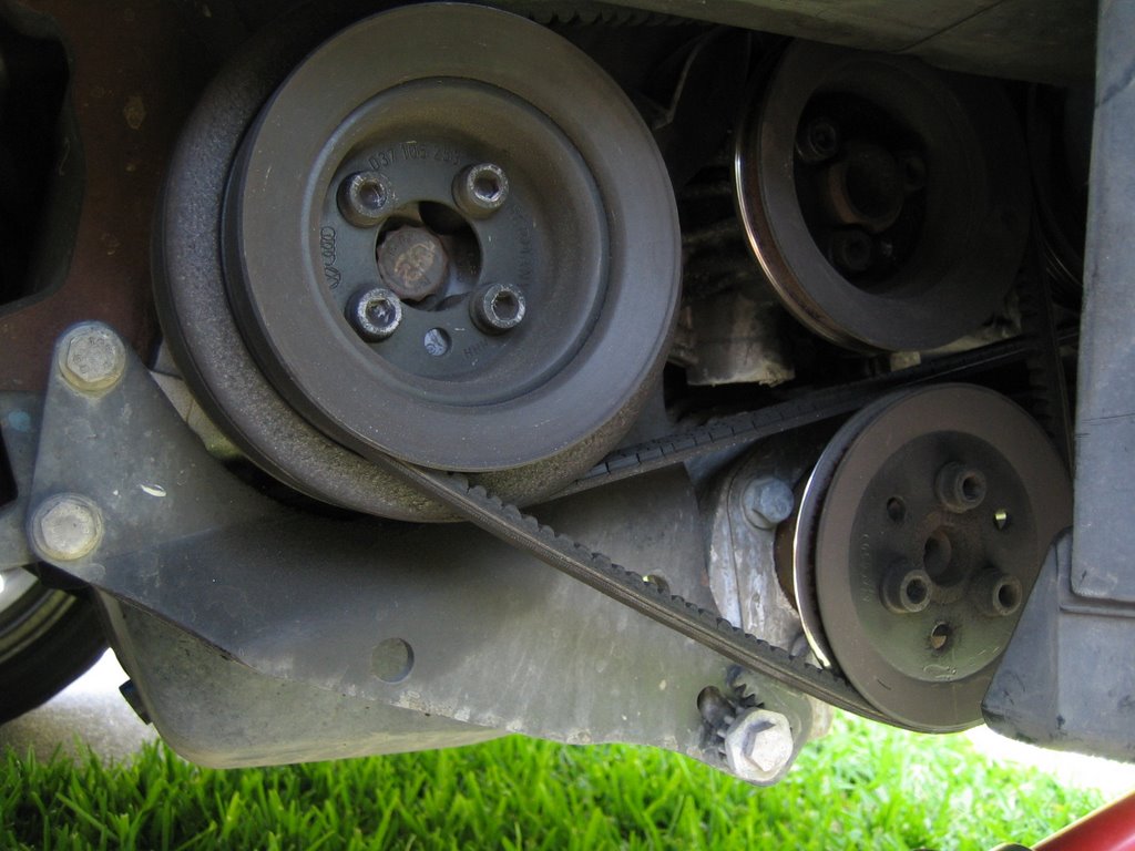 figure 14 |  figure 15 |
Remove Lower Timing Belt Cover
Alright, with the crank pulley out of the way we can take off the lower timing belt cover. There are four bolts we'll have to access.
The first two are located directly in front of you as your looking at where the crank pulley used to be. I think the're 5MM Hex bolts. Remove them.
The next bolt is up top near the cam sprocket. It's a 1/2" (or 10 mm?) bolt.
The last is a nut that needs to be removed that is hidden midway down near the water pump. You'll have to reach to see, but it's there.
With the lower portion of the belt cover off, we have full access to the timing belt and can see the three main sprockets: the cam sprocket up top, the distributor sprocket in the middle, and the crank sprocket down low.
Replace Timing Belt
To remove the timing belt, release the tension on the timing belt tensioner by unscrewing its 13mm nut a bit. Once the tension has been released carefully slide off the timing belt doing your best not to move any of the three sprockets.
Slide on the new belt, but don't re-tension it. Leave it slack.
Verify TDC Alignment
Ok, at this point we'll verify that the Cam, Distributor, and Crank are all aligned at TDC.
The cam hould already be close to TDC. To set it at TDC line up the sprocket "valley" between the "OT" with the "OT" arrow on the engine block. See Figure xx.
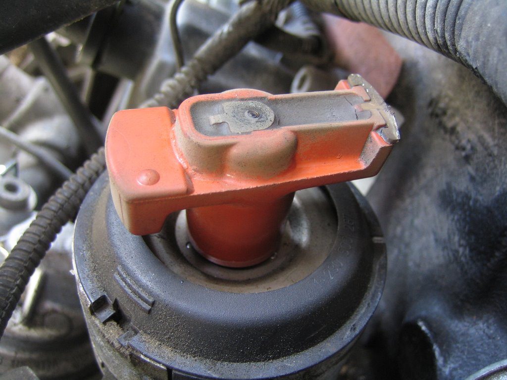
To set the distributor at TDC take the distributor cap off and line up the dirtributor arm with the small groove in the distributor housing. The distributor arm should be facing the engine block. See Figire XX. Once aligned, take a bright permanent marker or whiteout and make a TDC reference on the distributor sprocket.
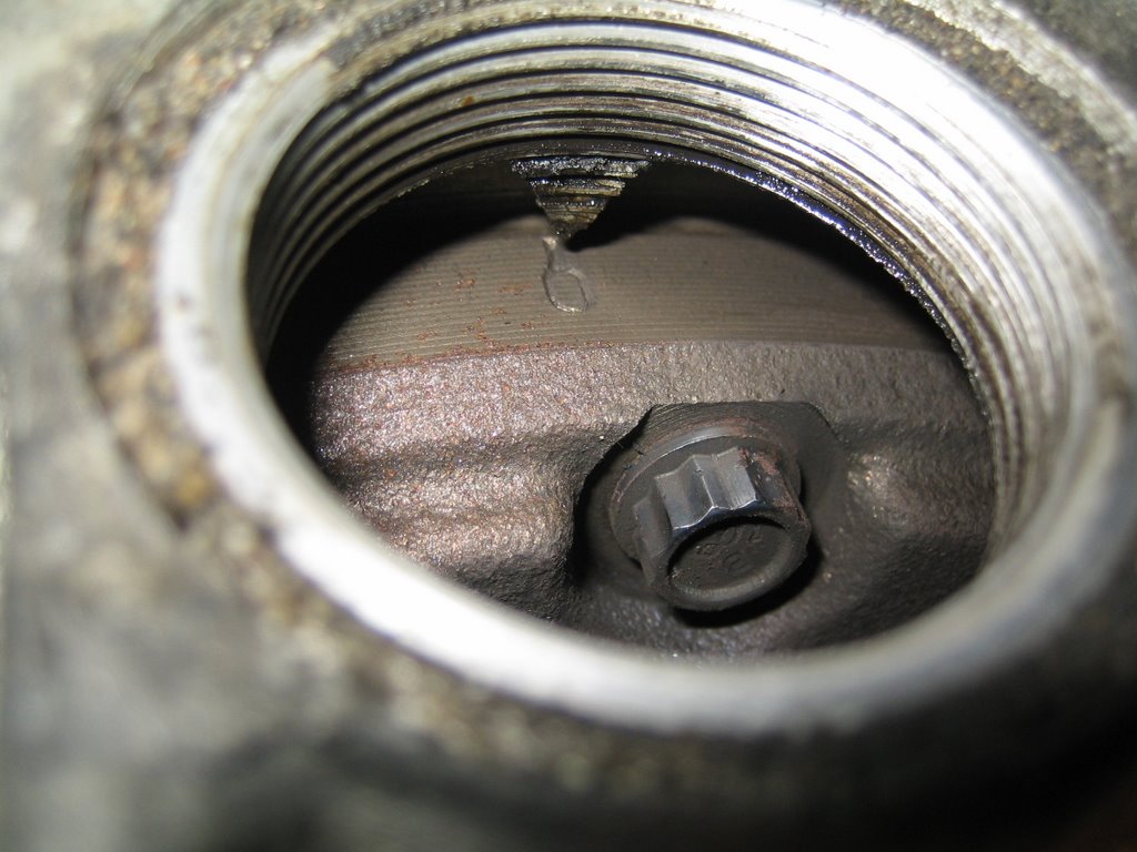
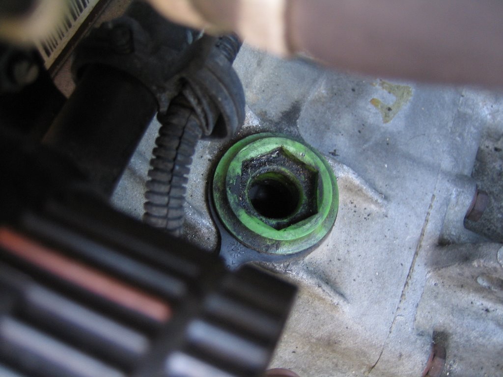
To set the crank at TDC remove the green plug on the [transaxle?] housing. The flywheel should be visible. There is a small mark on the flywheel that, when aligned with the "V" on the opening, sets the crank at TDC. See Figure XX.
Put It All Back Together
10:58 AM
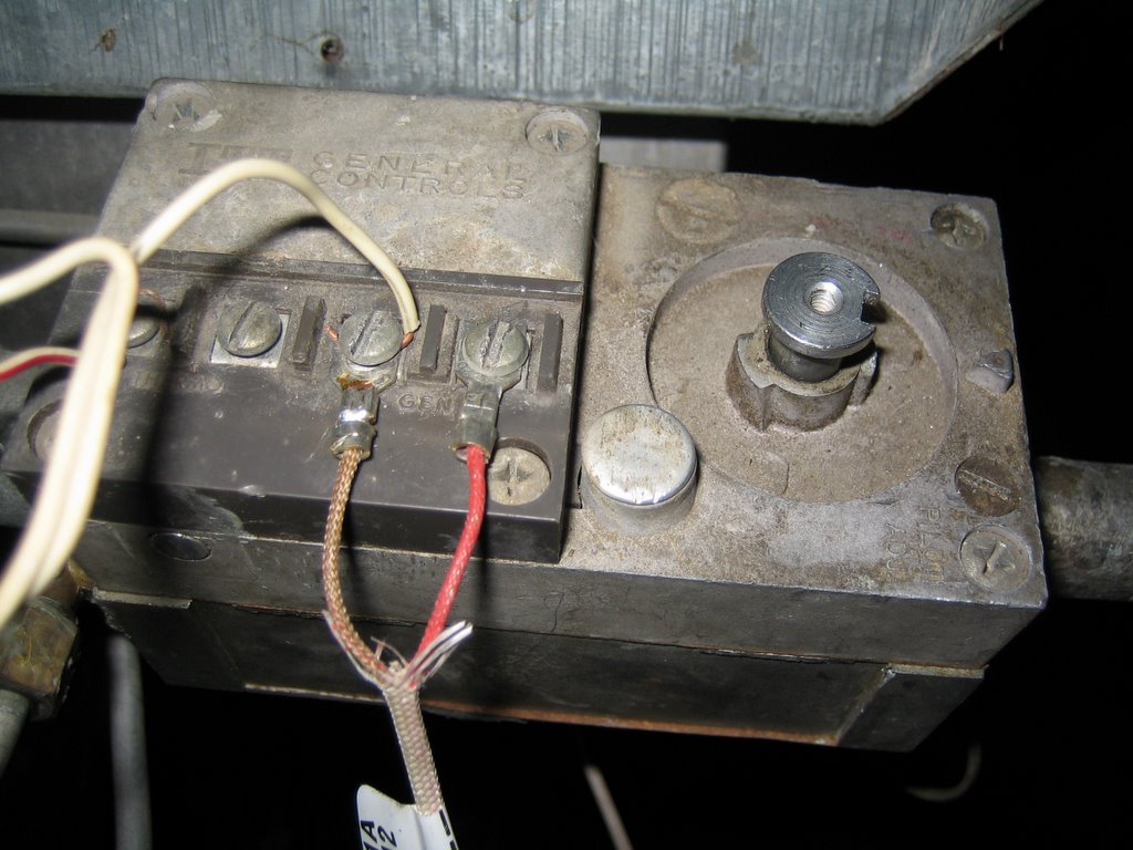
The pilot light won't stay lit. Replaced the thermocouple (technically a 750mV thermo-generator); still doesn't work. Hmm. I'm assuming this means it's most likely the gas valve that's gone bad.
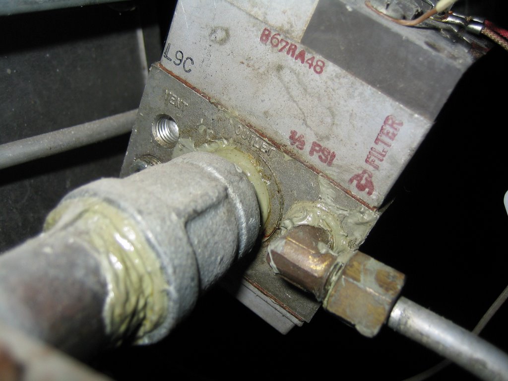
From what I can tell, this is an ITT General Controls milivolt gas valve, 0.5 psi, 750mV. It has 1/2" mains and a 1/4" pilot line.
I googled what appears to be the part number: B67RA48. I found this site which claims the Robert Shaw 700-502 is a suitible replacement; I found it for $80 at Grainger.
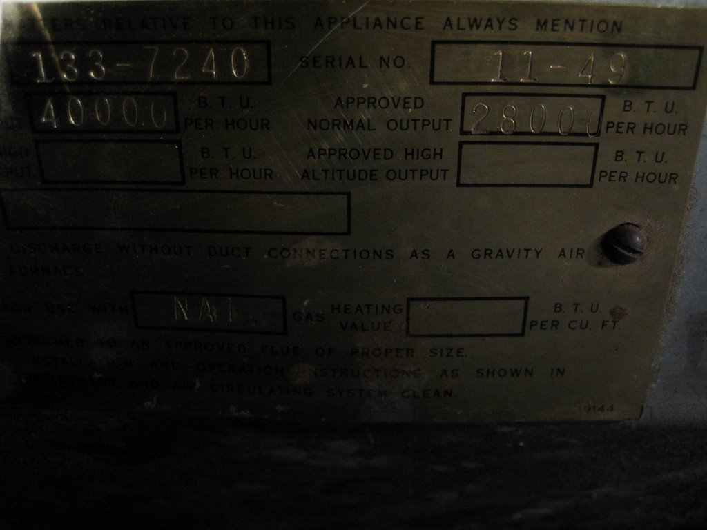
The furnace manufacturer is Homart by Sears, model 133-7240. The serial number is 11-42. Normal input is 40000 BTU, output is 28000 BTU.
10:57 AM
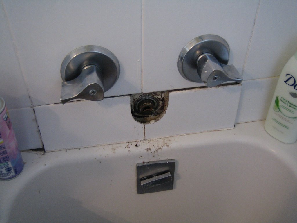
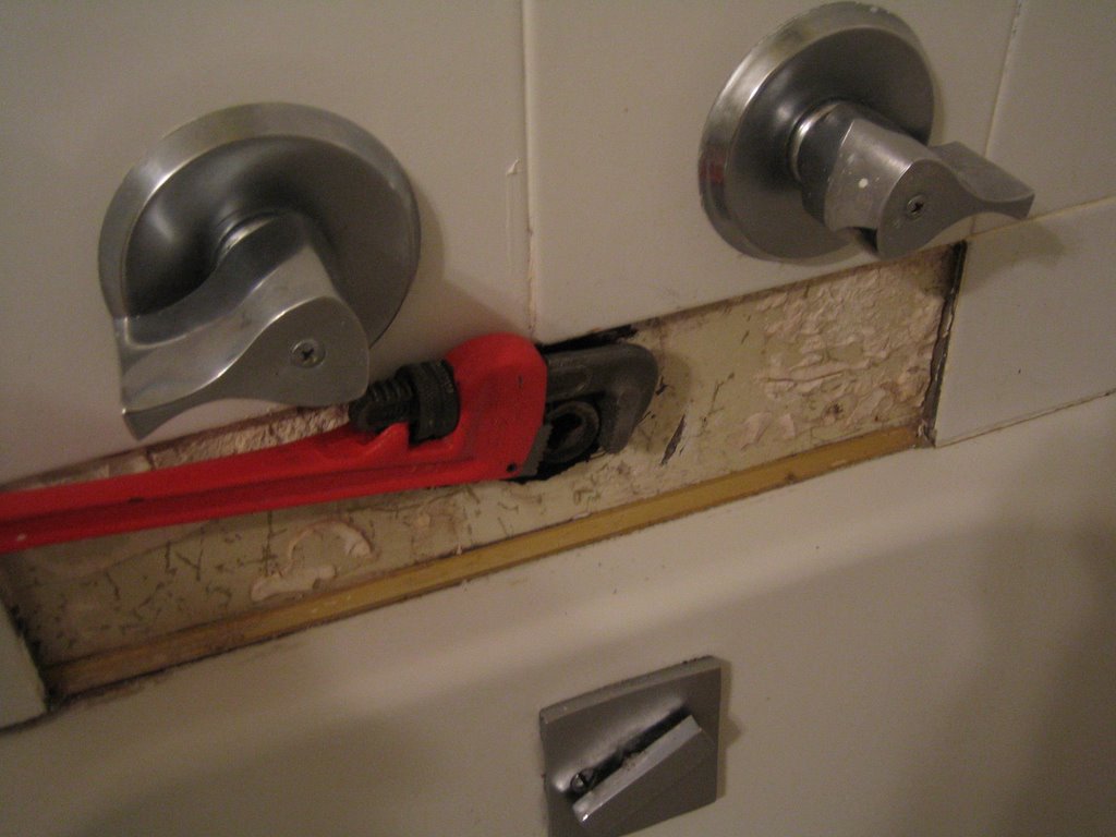
Step 1: Remove Faucet

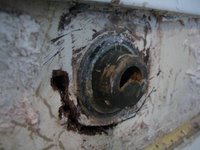
Using a plumber's wrench, the faucet head was twisted off. It snapped off instead of twisting. Hmm.
A closer look at the fixture reveals a strange non-threaded fitting. 40's? 50's? 60's? Ugh.
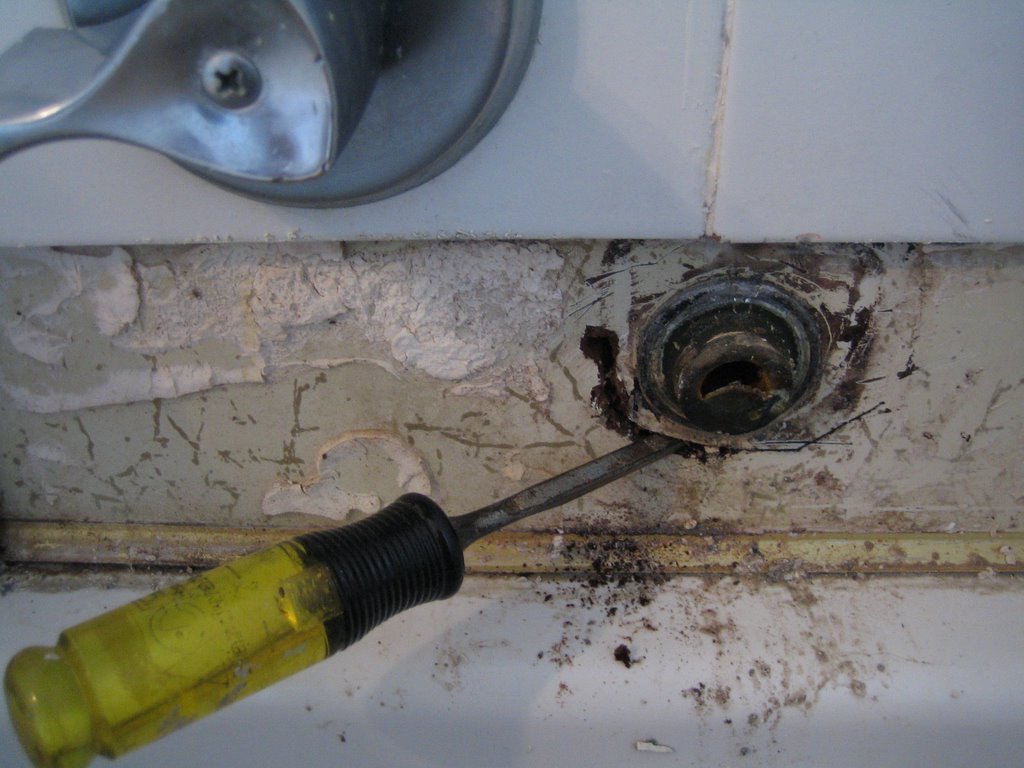
Step 2: Remove Tiles

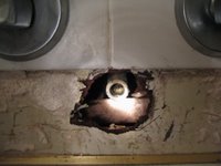
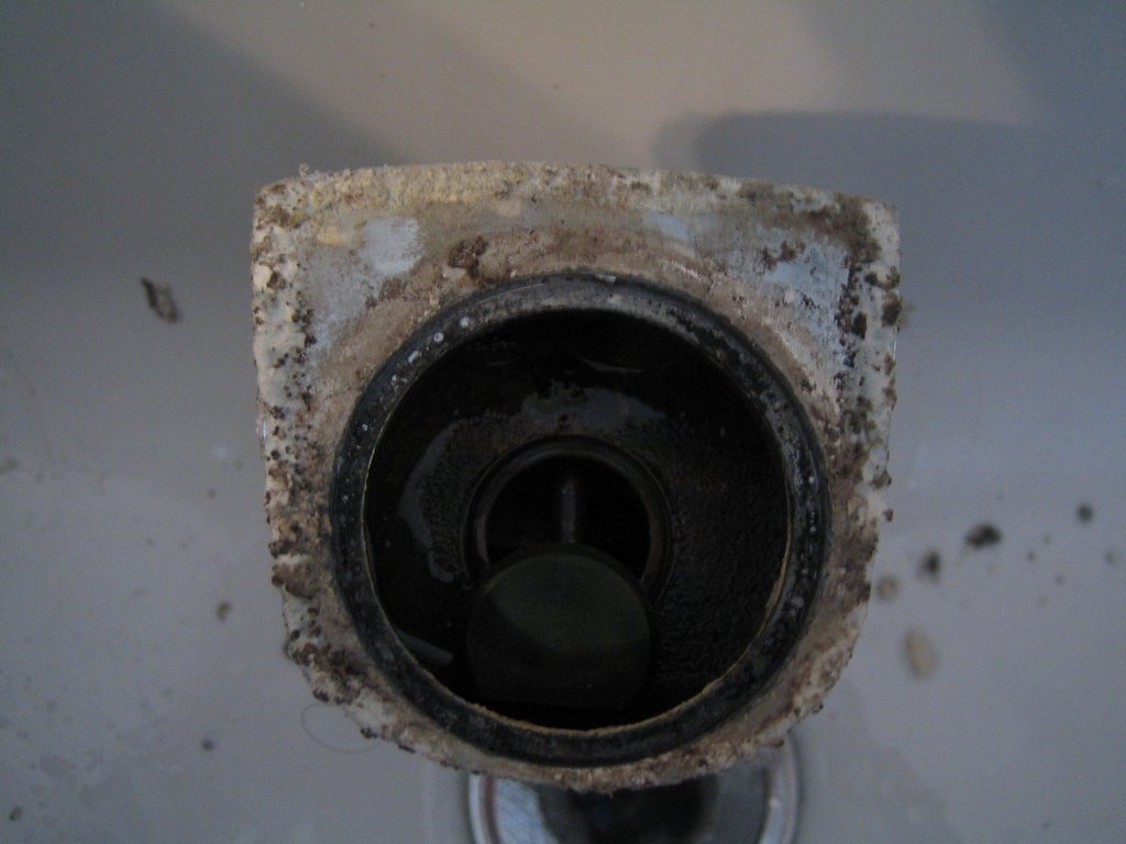
Use a chisel to remove grout and carefully remove surrounding tiling.
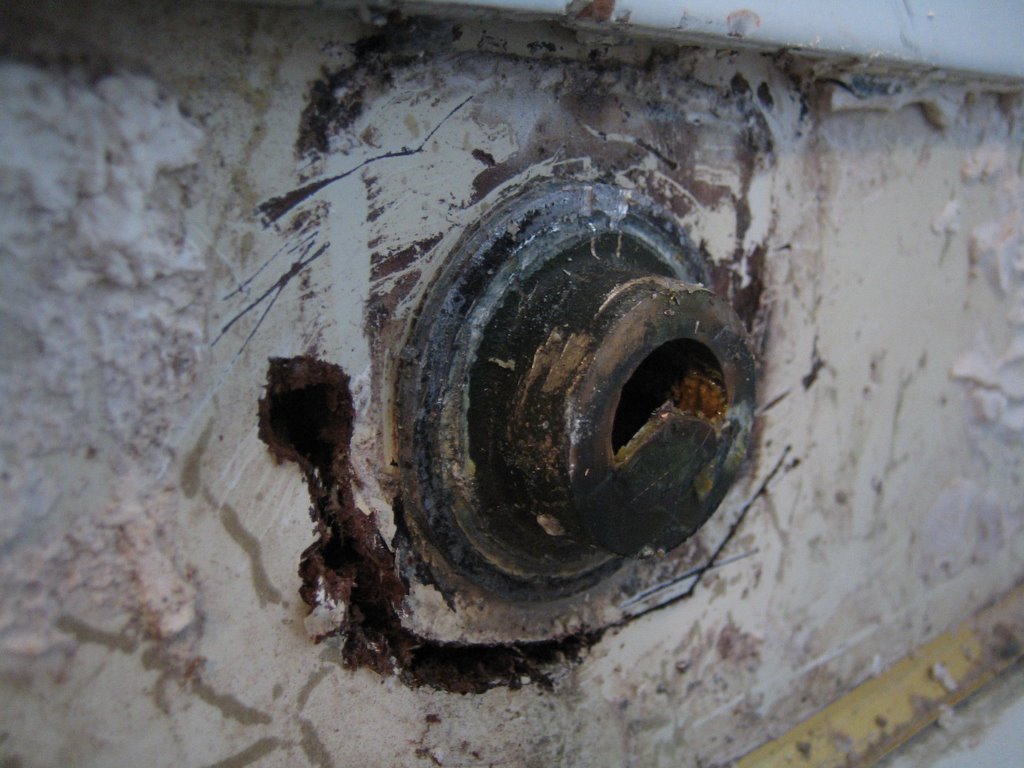
Now the male end of the strange non-threaded fitting is more visible. It's brass, and it won't budge.
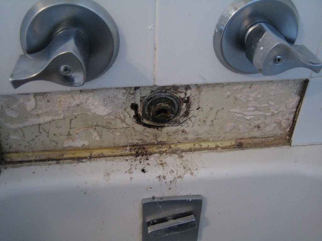
Step 3: Begin Removing Backing

What appears to be 40's/50's wallboard is easily removed with a chisel.
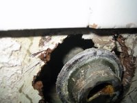
Now the fitting is more exposed and piping is visible behind the wallboard. The fitting appears to be part of the pipe neck, but it's hard to tell.
Step 4: Remove Faucet Pipe

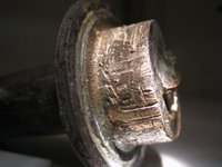
Using a plumbers wrench the faucet pipe is wrenched off. Hard to get a hold on that darn fitting!
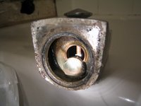
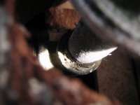
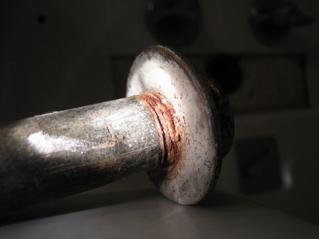
The fitting has been completely removed without damaging other tiles. Whew.

A nice closup of the mystery fitting. Looks like it was once an accessory fitting screwed on the end of the 1/2" pipe. It has since rusted solid. Strange - any ideas anyone?!
Using a plumber's wrench, the faucet head was twisted off. It snapped off instead of twisting. Hmm.

A closer look at the fixture reveals a strange non-threaded fitting. 40's? 50's? 60's? Ugh.
Step 2: Remove Tiles
Use a chisel to remove grout and carefully remove surrounding tiling.
Now the male end of the strange non-threaded fitting is more visible. It's brass, and it won't budge.
Step 3: Begin Removing Backing
What appears to be 40's/50's wallboard is easily removed with a chisel.

Now the fitting is more exposed and piping is visible behind the wallboard. The fitting appears to be part of the pipe neck, but it's hard to tell.

Step 4: Remove Faucet Pipe
Using a plumbers wrench the faucet pipe is wrenched off. Hard to get a hold on that darn fitting!

The fitting has been completely removed without damaging other tiles. Whew.
A nice closup of the mystery fitting. Looks like it was once an accessory fitting screwed on the end of the 1/2" pipe. It has since rusted solid. Strange - any ideas anyone?!
